Home-made Rose Engine lathe
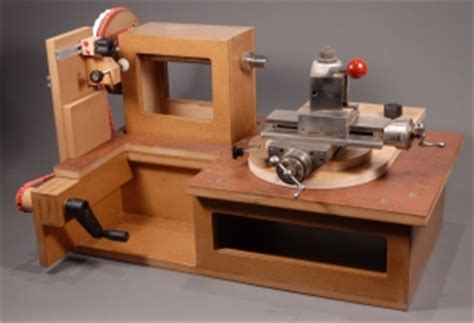
The inspiration for building a Rose Engine lathe came from one of the Talking Turning sessions run by the AWGB where there was a presentation by a member of the Society for Ornamental Turners (https://www.the-sot.com/). Whilst I would like to have a Holtzapfell lathe my budget won’t stretch that far. So, searching around the internet I found several examples of homemade lathes the one that got me thinking about making such a lathe was the article by John Magill on making one from half a sheet of MDF (https://www.rogueturner.com/mdf-rose-engine.html). So as a result, I decided to make one with some help from Jeff who is a friend and superb engineer. The following is the design we came up with. This page https://www.otbok.info/index.php?n=Main.MakingARoseEngineLathe has several examples of other home-made Rose Engine Lathes.
Metal work parts.
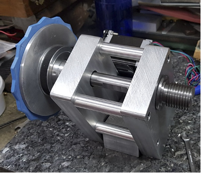
Jeff is semi-retired and he has a full engineering workshop in his garage and basement. He looked at the various home-made designs on the links above and on YouTube and other sites and we discussed a suitable design using elements from all that we researched. The two aluminium end frames have bearing top and bottom. The top bearings are larger as they carry the weight of the chuck and workpiece and the bottom ones are just to allow the frame to rock.
Electronics
The original design by John Magill was a hand operated machine and given the comments by some users it seems that it can be difficult to get a smooth movement of the workpiece and so a stepper motor was a better bet as the drive mechanism. A stepper motor needs some electronics to drive it. I found a video on YouTube about using an Arduino Uno micro controller to be the software driver for the stepper motor (https://youtu.be/iY_4YOlpqyI) and I used the software and circuit diagram in this video and the instructions on the website (https://dronebotworkshop.com/big-stepper-motors/). I already had an Arduino Uno that I had bought some time ago but was not using in a current project, these cost about £17 from Amazon as a kit with additional components. I needed a Nema 23 Stepper Motor €29 and a stepper motor controller €12 both from Amazon. The other couple of components I bought from a local electronics shop but all are available on Amazon. The power supply for the stepper motor and the Arduino is an old computer power supply slightly modified as per the instructions on a video on YouTube (https://youtu.be/n_A-jkpjpcM) and on the website https://dronebotworkshop.com/atx-bench-supply/. The drive pulleys came from AliExpress as a pair and have a 6:1 ratio and cost €13.
I found an issue with the micro controller. I had supplied it with 5v from the power supply to the power socket on the Arduino and the stepper motor did not run. I plugged the USB cable into my laptop from the Arduino and the stepper motor started turning. On checking online the power connector on the Arduino requires 9-12v not the 5v that I was feeding it, even though when only connected to the USB connector it gets 5v from the USB. I swapped the power feed to the 12v side of the power supply and the stepper turns perfectly. If I had done my research properly I could have probably used just a 12v 3 to 5amp power supply rather than converting a computer multi voltage power supply.
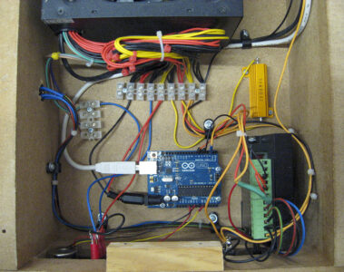
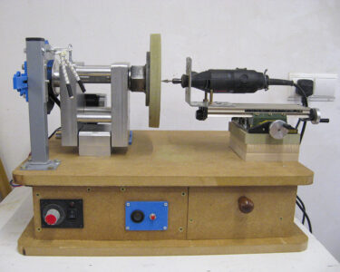
The Arduino micro controller is the blue board in the centre and the stepper motor controller is the black box on the right with the green connector on the top.
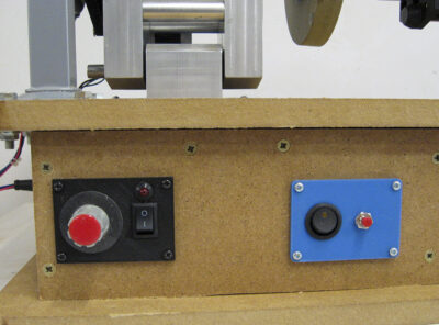
The black panel on the left has the speed control knob and the on/off switch and warning light for the stepper motor. The blue panel on the right has an illuminated on/off switch for the external 12v supply and the push button changes the direction of the stepper motor.
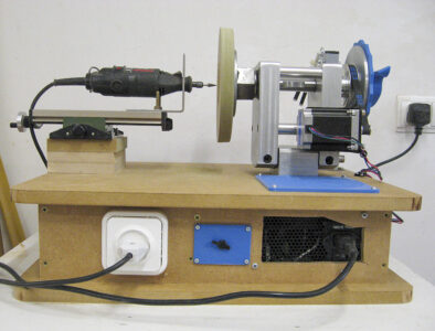
The rear panel has a 240v socket to power the Dremel, the blue panel houses an external 12v power socket for the laser engraver and the vent on the right side is for the hot air from the power supply as well as the 240v mains inlet socket and on/off switch.
At a later stage I am going to connect my 3D printer laser engraver instead of the Dremel to do some laser engraving.
Rosettes
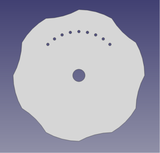
There are many examples of rosettes available online (some at https://www.otbok.info/index.php?n=Main.Rosette) and from these I drew inspiration. I designed some of my own in FreeCAD (https://www.freecadweb.org/) which is an open-source CAD package. I then converted these drawings into 3D models and printed them on my 3D printer. I decided on 150mm diameter for my rosettes and this is an example of one of them:
I also designed and 3D printed a ‘rubber and rubber mounting’ to work on the rosette as well as the panels for the switches and connectors and the vent grill for the power supply.
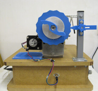
The end view showing the rosette in place resting against the rubber. The stepper motor is on the left and the cable from it plugs into the baseboard so that the top board can be easily removed to access the electronics. The blue grill is an air inlet for the power supply I will have to be careful about wood dust entering this. The bungy cord rubber elastic keeps the rosette pressed against the rubber. The row of small holes on the rosette are for phasing the rosette so that different overlapping patterns can be made.
Baseboard
The baseboard is made from some MDF sheet with the electronics mounted between the top and bottom board. It also has storage drawer for additional rosettes. I made a mounting for the Proxxon cross slide that I bought some years ago on eBay and had never used. I made a suitable mounting for a Dremel to fit on the cross slide to cut the pattern into the wood.
The finished unit.
Refinements
I will use this version for a while before I make any changes but changes that I am currently considering are:
- Removing the computer power supply and replacing it with a 12v 5amp laptop type power supply. This will remove the need for the power supply vents and remove the potential for dust to enter the power supply
- The cross slide that I have only has a small amount of front to back movement so I will either replace it or alter the baseboard to allow it to be mounted in multiple positions
- Beef up the Dremel mounting as it has some flex
- Find a suitable spring to replace the bungy cord
I am sure that in use I will find some other enhancements are needed like the replacement of the Dremel with a small router or CNC motor and collet.
UPDATE: I have now changed the cross slide and dremel see the article here.
Costs
I was very lucky in that Jeff made all the metal parts for me and did not charge me. I already had some of the electronics pieces, the Dremel and the cross slide so it has cost me around €70 for the MDF and the parts that I had to buy as well as some time to build and debug it all. It could have been made for less by using the smaller power supply, making the speed and rotation direction fixed.
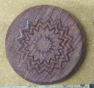
Day 1 result
I had a piece of side grain Bubinga with a chucking point on it in the scrap bin so I had a little play with the rosette in the photo above and this is the result. I look forward to doing some proper work with it over the coming weeks.